The first objective was to get a working printer port on my bench. I have a little atom based EEEPC out here in the workshop with no printer port on it to speak of. Thats where a usb to printer port adapter comes in handy. I admit I was keeping a little usb-to-centronics printer adapter (36 pin) around, looking for the right project. For those that don't know, the Centronics Printer was one of the first peripherals for use with the parallel printer port, but now the name usually refers to the pinout style rather than the Centronics Printer Company these days.


While the style is a centronic printer (36 pin) rather than the (25 pin) printer ports we come to see on the back of PCs, this adapter still shows up as a printer port. In Linux after loading the driver with modprobe ppdev and unloading the line printer driver with rmmod lp, this gives you a printer port to address with tjtag at /dev/parport0.

The next step was to break out the pins of the printer adapter in a logical fashion. After removing the shielding from the printer port side, the pins were bent outward and pre-tinned. I have some pop-in standoff-thingies in my parts box that were just asking to be used in this project.
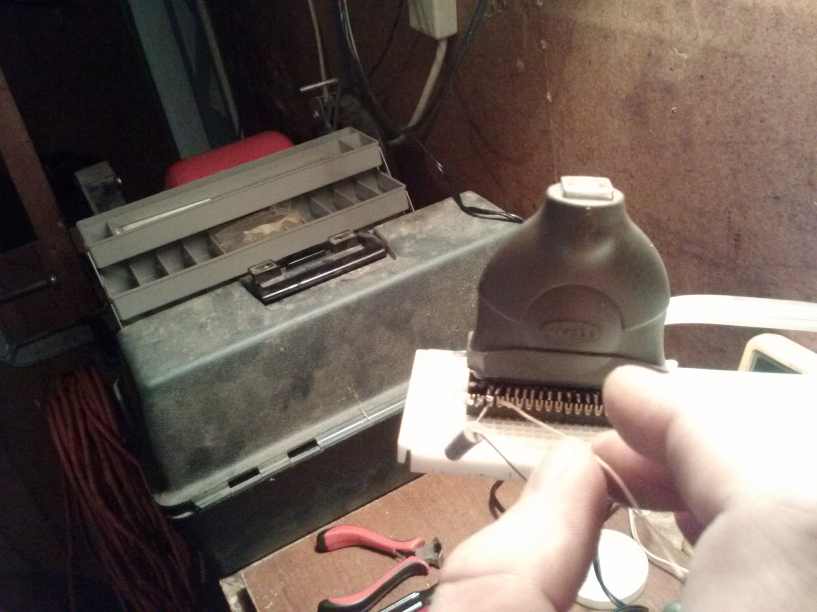
I use them as pin headers for plugging right into a breadboard. After the whole thing was glued and soldered into place, a trip to the bench grinder cleaned up the edges. The printer port fits nicely into the breadboard, and is now a modular component to my bag of tricks.

My next step, was to create a cable header for attaching to the external device's JTAG pinouts. Since I was going to use it on more than one router, I wanted to make something durable as well as modular, so I opted on making a reusable 7 wire cable with a pin header to plug in my breadboard too.


I've got something special in mind for at least one of these routers and a 150cc ultralite motorcycle/scooter sitting here in my garage. To be sure I'll showcase my work over the next few posts.
No comments:
Post a Comment