Friday, August 16, 2013

Keeway Hacker 150cc Scooter + Linksys WRT54G Router Running DD-WRT

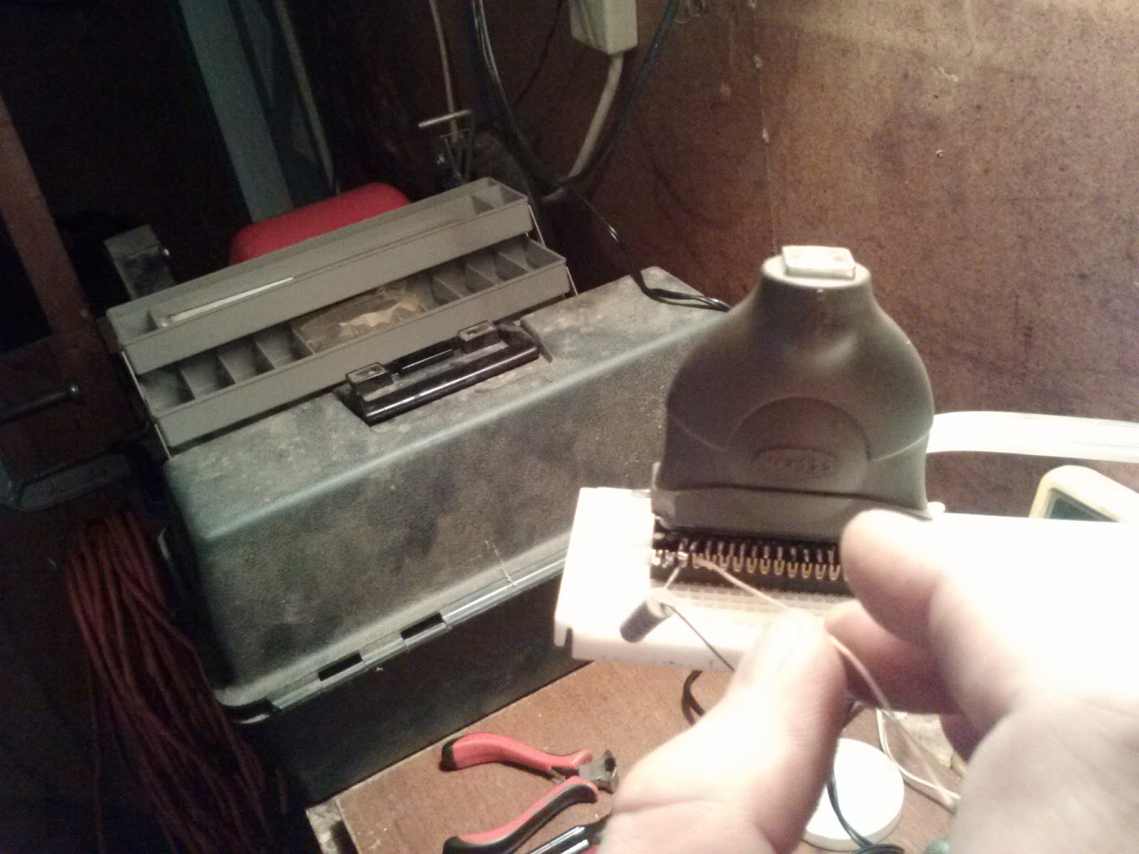
Today I am looking for the right place to mount a WRT54G router in my 150cc Keeway scooter.  In the last post I built a JTAG cable to revive some Linksys routers.  Not only did I revive a WRT54G, I ended up making a great USB parallel port breakout for use with a breadboard.  


So today, I set off to see whether or not a Linksys router, running DD-WRT, could find a spot somewhere in my Keeway Hacker 150cc Scooter.  With a name like that I just couldn't resist.  I had spent a few days hunting for the best place.  I did not, just want to throw mount it under the seat.  I use the compartment for my spare passenger helmet and did not want to give it up.  Also, I wanted the router completely concealed.  In my search I ended up removing the whole seat.  I was thinking of mounting it around the inside of the body where the tail brake light is located or toward the gas tank.  However, those locations just did not have enough real estate.  


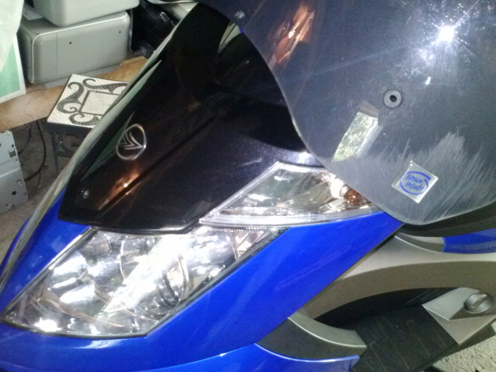
Finally, looking under the front "hood" compartment of the scooter.  I managed to find that by turning the router upside down there was just the right amount of space.  The fit was extremely tight but by removing one antenna and then maneuvering the router into place it would make it.


I was able to screw the antenna back on, once the router made it all the way in.  In the end I managed to find a great spot.  I liked it so much I wired up power and five minutes later I can close it all up.  Now I can play around with the little router from any computer on the network.


This project gave me some good ideas for future projects.  Making the tail brake light completely addressable and controlling it with aforementioned router, for one.  And maybe a temperature and RPM sensor for the engine as another.  I have a lot planned for this little scooter.  My next go at this will probably be to add a SD card reader to the router and populate the serial port(s).


Tuesday, August 6, 2013

Jtag Cable for Nefarious Deeds

I recently found myself with a stack of defunkt linksys routers and a need to reflash their "CFE.bin" files.  While not completely bricked the tftp method was a "no go" at bringing these bad boys back from the grave.  After the customary few hours on Google, and counting up the parts I had on hand, I settled for making a simple jtag cable rather than a full blown buffered wiggler with selectable voltage source (which I was really leaning toward).

The first objective was to get a working printer port on my bench.  I have a little atom based EEEPC out here in the workshop with no printer port on it to speak of.  Thats where a usb to printer port adapter comes in handy.  I admit I was keeping a little usb-to-centronics printer adapter (36 pin) around, looking for the right project.  For those that don't know, the Centronics Printer was one of the first peripherals for use with the parallel printer port, but now the name usually refers to the pinout style rather than the Centronics Printer Company these days.


While the style is a centronic printer (36 pin) rather than the (25 pin) printer ports we come to see on the back of PCs, this adapter still shows up as a printer port.  In Linux after loading the driver with modprobe ppdev and unloading the line printer driver with rmmod lp, this gives you a printer port to address with tjtag at /dev/parport0.


The next step was to break out the pins of the printer adapter in a logical fashion.  After removing the shielding from the printer port side, the pins were bent outward and pre-tinned.  I have some pop-in standoff-thingies in my parts box that were just asking to be used in this project.


I use them as pin headers for plugging right into a breadboard.  After the whole thing was glued and soldered into place, a trip to the bench grinder cleaned up the edges.  The printer port fits nicely into the breadboard, and is now a modular component to my bag of tricks.


My next step, was to create a cable header for attaching to the external device's JTAG pinouts.  Since I was going to use it on more than one router, I wanted to make something durable as well as modular, so I opted on making a reusable 7 wire cable with a pin header to plug in my breadboard too.


Once I had all the parts created, it was a cinch to wire up something on the bench to reflash the firmware.  I didn't have 100 ohm resistors but I did have plenty of 200 ohm ones, putting two in parallel gives me the 100 ohms I was looking for, for each line.


I've got something special in mind for at least one of these routers and a 150cc ultralite motorcycle/scooter sitting here in my garage.  To be sure I'll showcase my work over the next few posts.